
Samina Ismail
Associate Professor, Department of Anesthesiology, Aga Khan University, Karachi (Pakistan)
Correspondence: Dr. Samina Ismail, Associate Professor, Department of Anesthesiology, Aga Khan University Hospital, Stadium Road, P. O. Box 3500, Karachi 74800 (Pakistan); Phone: +92 21 3486 4639, +02 21 3493 0051, Extension 4631, 4331; E-mail: samina.ismail@aku.edu
ABSTRACT
Central neuraxial blocks (CNB) are the preferred blocks in the practice of regional anesthesia. Palpation of the anatomical landmarks is used for the identification of the space, which is not always the best method when CNB is performed in overweight patients or patients having atypical spines like scoliosis. Ultrasound (US) has recently been utilized to facilitate CNB. However, CNB US can be difficult, because the structures need to be visualized by US are surrounded by bones, which do not allow ultrasound rays to pass through. Therefore in order to allow deeper penetration, the ultrasound probe used for CNB is a curved probe of low frequency of 2-5 mHz, as it allows deeper penetration at the expense of image resolution. There are two scanning planes; transverse and longitudinal which supplements each other. US for CNB helps in determining the intercristal line, exact intervertebral level, midline, ideal point of insertion, distance to ligamentum flavum and needle trajectory. US for CNB has improved patient safety by decreasing the number of attempts, chances of dural puncture and damage to conus medullaris. It has also improved patient satisfaction and has proved to be an ideal learning tool for the trainees.
Key words: Regional Anesthesia; Spinal Injections; Spinal Puncture; Anesthesia, Spinal; Anesthesia, Epidural; Anesthesia, Conduction; Ultrasonography
Citation: Ismail S. Ultrasound Guided Central Neuraxial Block. Anaesth Pain & Intensive Care 2015;19(3):361-365
INTRODUCTION
Among regional techniques, central neuraxial blocks (CNB) are the most commonly performed regional anesthesia technique performed by the anesthesiologists. CNB includes spinal, epidural, combined spinal epidural (CSE) and caudal blocks in perioperative, obstetric and chronic pain practice.1 Palpation of the anatomical landmark is the usual method employed for the identification and placement of CNB. However, in situation of difficult anatomical landmark like obesity, pregnancy, spinal deformity and prior instrumentation of spine, there is high chance of failure with use of clinical method of palpation. Previous investigations on CNB have shown technical difficulty in 15%, more than five attempts in 10% and failed in CNB in 5% of cases.2, 3 To improve success there has been a recent increase in interests in using ultrasound (US) to guide the performance of CNB.
The aim of this article is to provide relevant information of using US for CNB to anesthesiologist to facilitate its clinical usage in every day practice of performing CNB. This article will elaborate as why US guidance is needed for CNB; its use among anesthesiologist and scanning technique and practical aspects of performing US guided CNB.
WHY ULTRASOUND SCANNING IS NEEDED FOR CNB?
Bedside spinal ultrasound can improve safety in performing CNB, as it has proved to be helpful in identifying the correct position of the puncture.4-6 In addition needle injury to the spinal cord may be avoided, which is a rare but preventable complication.1 However, identification of the conus medullaris is not possible with the available US machine, therefore needle injury can still occur if the spinal cord is at a level lower than the normal level.7
Other advantages of US include absence of radiation, ability to perform dynamic evaluations, real time imaging, fewer attempts, decrease chance of dural tap and post dural puncture headache which follows it, and increase in the over all percentage of patient satisfied with the management. 8 Taking into consideration these advantages of US guided CNB; the National Institute of Clinical Excellence in the United Kingdom has recommended routine use of US for epidural insertion.
ULTRASOUND USE FOR CNB
US for CNB has not been accepted as a routine use in clinical practice. The reason is poor understanding of US imaging among the anesthesiologist and inability to visualize the anatomy of spine using US machine. In addition use of ultrasound for CNB is complex, because the elements to be visualized by US are located deep within the bones, which do allow the full penetration of structures. In addition low utilization of US is due to poor understanding among the anesthesiologists on how to interpret US image of the spine. As a result a survey of 150 anesthesiologist in the UK showed that >90% has never used US to image CNB.9
US MACHINE FOR CNB BLOCKS
As the structures needed to be visualized by US are deeper and enclosed within bony framework of vertebral column, a curved US probe of low frequency ranging from 2-5 MHz is used to allow deeper penetration of US beam but at the expense of poor image resolution
SCANNING PLANE
The two scanning planes used for the US of CNB are longitudinal axis (sagittal scan) and transverse axis (axial scan). These two scanning planes can be done in sitting, lateral and prone positions. Each scanning plane has its own advantages but it is advisable to scan in both planes as they complement each other during US scanning of the spine.
When US probe is positioned in the transverse plane, the US image obtained appears like that of a flying bat (Figure 1); and when placed in a longitudinal plane, the image appears like that of a saw (Figure 2).
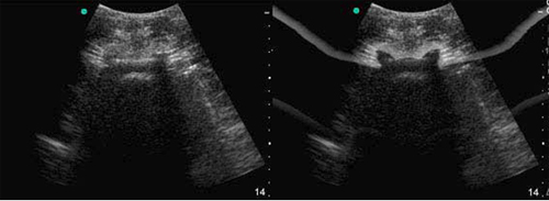
Figure 1: Ultrasound probe in the transverse plane gives the image of “flying bat”
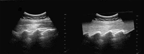
Figure 2: Ultrasound probe on the sacrum and multiple interspaces in the longitudinal planes gives the image of “saw” pattern.
Longitudinal Scanning can be done in the sitting, lateral or prone position. Patient lumbosacral spine is flexed and the transducer is placed at a distance of one to two centimeters lateral to the spinous process. The orientation marker on the ultrasound probe should be directed in the cephalad position (Figure 3). The transducer is slightly tilted medially, which allows the US beam to enter through the interlaminar area which is the wider area of the spinal canal .The first structure identified is sacrum, which appears as a flat line and hyper echoic in nature on US having a large dark acoustic shadow immediately anterior to it. When the transducer is moved in a cephalic direction a gap is seen, which is the interspace between sacrum and L5 lamina (Figure 4).
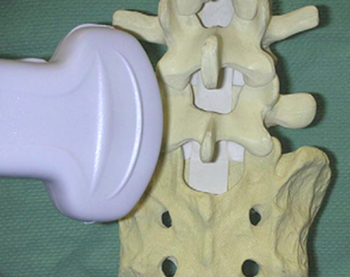
Figure 3: The ultrasound probe is placed in the longitudinal plane in a paramedian position.
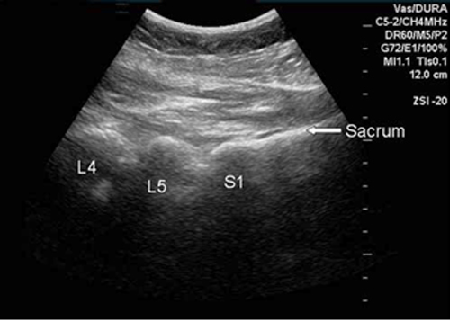
Figure 4: Sacrum is seen as a continuous hyper echoic line with breaks as interspaces alternating with “humps” as lamina of different vertebrae
The structures observed in this plane are sacrum, lamina and interspaces at various levels. In addition other structures includes vertebral body, anterior dura matter, posterior dura matter, posterior longitudinal ligament, ligamentum flavum, CSF and the spinal canal. In the longitudinal view, ligamentum flavum and the posterior dura are seen clearly and this is advantage the longitudinal plane has over transverse plane (Figure 5).
Transverse Plane: In this plane the US transducer is positioned on the spinous process of the vertebral body (Figure 6). The US image of the spinous process and the bilateral lamina on this plane will appear as a hyper echoic line. The shadow anterior to it is dark acoustic in appearance, which results in completely obscuring the underlying spinal canal and thus the neuraxial structures (Figure 7). Therefore the transverse view is advantageous in identification of the midline, when it is not possible to identify the midline by palpation of the spinous process as in obese patients. This view however is not helpful for imaging the neuraxial structures, due to the anterior dark shadow obscuring the view of neuraxial structures.
To improve the visualization of the image, it is required to slightly tilt the transducer to align the US beam to pass between the adjacent spinous processes. Through the interspinous view, from the lateral aspect articular processes of the facet joints can be visualized and the structures seen in the midline from the posterior to anterior direction are ligamentum flavum, posterior dura, thecal sac, and the anterior complex (Figure 8).
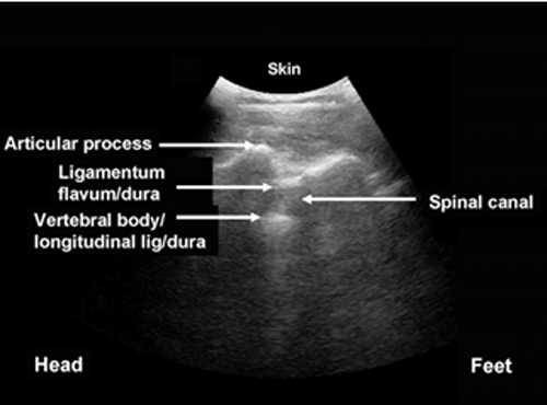
Figure 5: Structures identified in the longitudinal planes
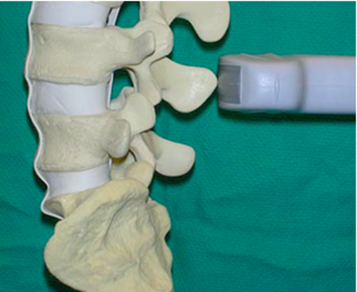
Figure 6: Position of the probe on the spinous process in the transverse plane

Figure 7: Spinous process in the transverse plane appears as a hyper echoic triangular shadow.
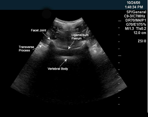
Figure 8: US probe at an interspace in the transverse plane; images seen are of transverse process, facet joint, ligamentum flavum and vertebral body.
INSERTION POINT FOR CNB IDENTIFIED BY THE US
The patient should be positioned for US in the same position as for the actual placement of an epidural. The intervertebral levels are determined in the longitudinal plane marked on the skin. By positioning the probe in the transverse plane, the ideal insertion point for each interspace can be identified, which is the intersection of the midline and the interspace. The identification of the spinous process in the transverse plane determines the midline, which is marked as a dot on the skin at the midpoint of the US probe when the image is centered on the screen. The best image of an interspace visualizing ligamentum flavum, ventral and posterior dura matter, posterior longitudinal ligament, vertebral body, transverse process and articular process can be obtained by moving the probe in a caudal or cephalad direction. Once the best image of the interspace is obtained, a mark is made on the skin at the width of the probe, which represents the interspace. The ideal insertion point can be marked on the skin by joining the vertical line intersecting the midline point and a horizontal line intersecting the interspace point. (Figure 9).
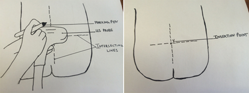
Figure 9: Determination of the insertion point in the transverse plane.
US FOR ATYPICAL ANATOMY
Atypical anatomy is associated with conditions like obesity, scoliosis etc. The scoliotic spine is asymmetrical with different images of the articular and transverse processes on each side, and not the mirror image as seen in the transverse plane in a patient with normal spine. The typical vertical line of the spinous process appear as an oblique line to one of the sides. The distance of the articular processes from the skin often appear at different distances with partial visibility of the ligamentum flavum. The reason for these US images of the scoliotic spine is due to presence of asymmetry at the level the abnormal interspace (Figure 10).
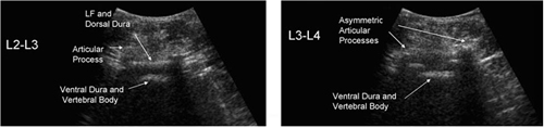
Figure 10: (Left): Sonogram at a level of normal interspace (Right): Atypical sonogram of different level of the same patient having scoliosis asymmetry at this level
CONCLUSION
US guided CNB although not routinely performed by anesthesiologist, is a best choice for the practice of performing safe CNB. It is especially beneficial in patients having atypical spine like scoliosis and also in conditions where identification by palpation is difficult like in obesity and pregnancy. It is non-invasive, safe, without radiation exposure, easy to use and provides real time images. A scout image helps in the determination of midline, ideal insertion point, level of intervertebral level, and distance to ligamentum flavum and trajectory for needle insertion. It has shown to decrease the number of attempts at CNB, patient satisfaction and important learning tools for the students.
REFERENCES:
- Cook TM, Counsell DM, Wildsmith JA. Major complications of central neuraxial block; report on the Third National Audit Project of The Royal College of Anaesthetists. Br J Anaesth. 2009 Feb; 102(2):179-90. [PubMed] [Free full text] doi: 10.1093/bja/aen360.
- Tarkkila P, Huhtala J, Salminen U. Difficulties in spinal needle use: insertion characteristics and failure rates associated with 25-, 27- and 29-gauge Quincke-type spinal needles. Anaesthesia. 1994 Aug; 49(8):723-5. [PubMed] [Free full text] doi: 10.1111/j.1365-2044.1994.tb04410.x.
- Seeberger MD, Lang ML, Drewe J, Schneider M, Hauser E, Hruby J. Comparison of spinal and epidural anesthesia for patients younger than 50 years of age. Anesth Analg. 1994 Apr; 78(4):667-73. [PubMed]
- Arzola C, Davies S, Rofaeel A, Carvalho JC. Ultrasound using the transverse approach to the lumbar spine provides reliable landmarks for labor epidurals. Anesth Analg. 2007 May; 104(5):1188-92. [PubMed]
- Carvalho JC. Ultrasound-facilitated epidurals and spinals in obstetrics. Anesthesiol Clin. 2008 Mar; 26(1):145-58. [PubMed] doi: 1016/j.anclin.2007.11.007
- Grau T, Leipold RW, Conradi R, Martin E, Motsch J. Efficacy of ultrasound imaging in obstetric epidural anesthesia. J Clin Anesth. 2002 May; 14(3):169-75. [PubMed]
- Margarido CB, Mikhael R, Arzola C Balki M, Carvalho JCA. The intercristal line determined by palpation is not a reliable anatomical landmark for neuraxial anesthesia. Can J Anesth 2011 Mar; 58(3):262–66. [PubMed] [Free full text] doi: 10.1007/s12630-010-9432-z.
- National Institute for Health and Clinical Excellence. Ultrasound Guided Catheterisation of the Epidural Space: Understanding NICE Guidance. January 2008. Available on https://www.nice.org.uk/guidance/ipg249 (Accessed on 28 July 2015)
- Mathieu S, Dalgleish DJ. A survey of local opinion of NICE guidance on the use of ultrasound in the insertion of epidural catheters. Anaesthesia. 2008 Oct; 63(10):1146-7. [PubMed] [Free full text] doi: 10.1111/j.1365-2044.2008.05697.x.
